Blogs » Business » Specification and wiring of computer switch mould
Specification and wiring of computer switch mould
-
Posted by tangram tangram - Filed in Business - 368 views
Switch mould, also called socket by some people, has different names, but it is actually the same item. It is a kind of socket that conforms to the special switching power supply on the computer display screen. It is mainly composed of an insulating layer base, a fixed key slot, a fork-shaped touch spring, a vertical jack and a horizontal jack. So what are the specifications of the power socket on the computer, and how to wire the switch mould on the computer, let's take a look.
Specifications of switch mould on the computer:
1. Switch mould is widely used in our life and can be seen everywhere, such as MP4, MP3, DVD, speakers, rice cooker, microwave oven heating, TV, electric fan, electronic device body fat scale, electronic device body scale, electronic device Kitchen scales, mobile phones, car cut-off phones, telephones and other audio-visual products, electronic products and electrical products. In addition, some of them will be used in medical equipment, fitness equipment, security equipment, computer machines, etc.
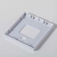
2. After talking about so much related professional knowledge about switching power supply, what is the specification of power socket. How to connect the power socket wiring is all the questions that most people care about and require to master. There are many specifications for power sockets, and different products require different specifications for power sockets. The different specifications and specifications of power sockets are mainly due to the different types. The following is a detailed introduction to the typical and common types of switching power supplies of Best electronic devices and related specifications engineering drawings. The specification engineering drawings clearly indicate their related specification.
How to wire the switch mould on the computer:
1. First use a test pen to find the front
2. Turn off the power outlet
3. Connect one of the two holes in the front of the power switch, and then connect a 2.5CM2 insulated cable in series from the other hole to the socket below
4. Connect the L hole in each hole firmly.
5. Find the zero line and connect it to the N hole in the 3 holes of the socket immediately. 5. Find the ground wire and immediately connect it to the E hole in the 3 holes of the socket.
6. Note: The zero and ground wires cannot be inserted wrongly (generally, the socket should be connected to the grounding device on the left and right of the socket, otherwise, if the power-consuming equipment is plugged in, it will trip when it is turned on).
switch mould https://www.tangrammould.com/Wall-Gang-Switch-Mould.html